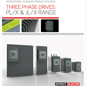
The PL/XD provides the same functionality as the integrated PL/X drive, except without the power stage. The PL/XD uses the same frame size as the PL/X 5 – 50 model and hence is extremely compact. The PL/XD provides all the world-class control features of the PL/X series. The PL/XD can control a 6 pulse 2Q bridge (6 thyristors), 2 bridges in parallel (12 thyristors) or a 6 pulse 4Q regenerative anti-parallel bridge (12 thyristors).
PL/XD Series
A digital stack controller built from the classic PL/X platform.
The PL/XD is used for controlling external 3-phase thyristor stacks for DC motors and slip-ring motors. It possesses the same functionality as the PL/X range, except that the output power stage is not included.
The PL/XD makes an extremely economical solution for users of very large power DC motors wishing to separate the control and power modules.
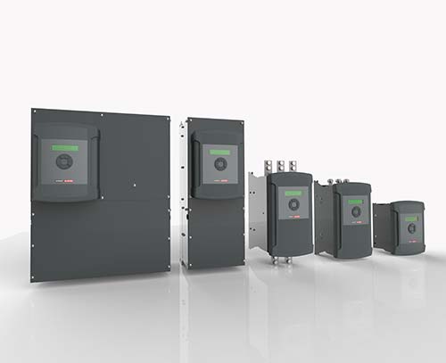
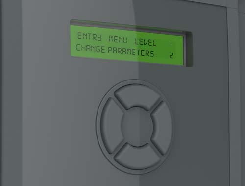
State-of-the-art Digital control
The PL/XD provides gate drive pulse for driving user supplied pulse transformers with primary pulse current up to 1.5A. The PL/XD can be supplied with supply voltages up to 690VAC as standard. There is also an integral motor field bridge with independent single-phase AC supply inputs for controlling fields up to 32A or 50A. Internal field supply input voltage is set at 480VAC.
Powerful Ethernet
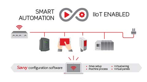
The PL/XD can be fully equipped with Drive.Web to enable the Industrial Internet Of Things (IIOT). Drive.Web distributed control technology uses Ethernet and powerful graphical tools to provide robust Programmable Peer Control (PPC) for drives and systems. Options for field bus systems include Ethernet, Profibus, CANbus, Modbus, DeviceNet and many more. The PL/XD is CE approved.
Other Features & Benefits
RATINGS
– Fully controlled variable field supply
ARMATURE VOLTAGE
– V armature = Vac x 1.2
FIELD VOLTAGE
– V field = 0 to 0.9 x Auxiliary AC Supply
AC SUPPLY VOLTAGE (VAC)
EL1 / EL2 / EL3 Synchronisation 3 phase 50-60Hz:
– 12 to 690Vac +/- 10%
EF2 / EF3 1 phase 50-60Hz:
– 100 to 500Vac +/- 10% for field power
Control 1 phase 50-60Hz:
– 110 to 240Vac +/- 10 for control power
PROTECTION
– Instantaneous over-current
– Field failure and over-current
– Motor over-temperature over-temperature
– Mains supply phase loss
– Mains synchronisation loss – Armature over-volts
– Speed feedback failure
– Stall protection
– Standstill logic
– Thyristor ‘trigger’ failure
– Digital output short circuit
INPUTS/OUTPUTS
ANALOGUE INPUTS
– 8 total (resolution 2.5mV+sign)
– All configurable
– All have programmable thresholds and 4 voltage ranges
– +/- 5/10/20/30V
– All inputs are over voltage protected and can also be utilised as digital inputs
ANALOGUE OUTPUTS
– 4 Total (resolution 2.5mV+sign)
– 1 armature current output – 3 configurable
– All outputs are short circuit protected
DIGITAL INPUTS
– 17 total
– All configurable
DIGITAL OUTPUTS
– 7 Total (24V logic 350mA total)
– Short circuit protected
– Over temp and
– over voltage protected
– All configurable
STANDARD SOFTWARE FUNCTIONS
– Full suite of centre winding macros
– Motorised pot simulator with memory
– 2x PIDs (undedicated)
– 2x Summers (undedicated) – 2x Filters (undedicated)
– Delay timer
– Current Profiling
– Spindle Orientation
– Jog/Crawl functions
– Dual motor swap
– Latch
– Linear or S ramp
– Slack take up
– Batch counter
– Draw control
– Auto self-tune current loop – 3 user programmable drive configurations
ALARM STATUS
– First fault latched and automatically displayed.
– Fault automatically saved at power off
MONITORING
– All analogue input voltages
– All digital input states
– All analogue output voltages
– All digital output states
– Tachogenerator voltage
– Motor armature current (amps)
– Motor field current (amps)
– Motor armature volts
– Output power
– AC supply volts
FIELD CONFIGURATIONS
– Fixed current
– Fixed voltage
– Field weakening
– Delayed quenching – Standby field value – Field economy
ENVIRONMENT
– Ambient operating temperature
– 0-40 ̊C (2050A 2250A 35°C) – 25 to +55 ̊C storage
STEADY STATE ACCURACY
– 0.01% Encoder feedback with digital reference.
– 0.1% Analogue tachogenerator feedback
– 2% Armature voltage feedback
– 0.01% Encoder + tach, encoder + AVF or encoder only feedback
– Maximum encoder frequency 100KHz
STANDARDS
CE marked to EN50178
– (low voltage directive)
EN50082-2:1995
– Immunity industrial environment
EN50082-1:1997
– Immunity residential commercial and light industry
EN50081-2:1993
– Emissions industrial environment (EN55011 Class A)
EN50081-1:1992
– Emissions industrial environment (EN55022 Class B)
– UL and cUL listed 12-630Amps – UL and cUL pending
650-2250Amps
SPEED FEEDBACK
Analogue tach
Encoder
Armature voltage
Encoder + Armature volts
Encoder + Analogue
COMMS
Rs232 as standard
Profibus available
DeviceNet available
CC-link available
EtherNet/IP available
Modbus available
CANopen available
drive.web Ethernet available

Downloads
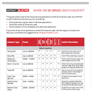
Where DC Digital Drives are used
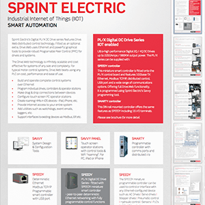
Sprint Electric DC Drives IIoT enabled

PL PLX Serial Comms Manual
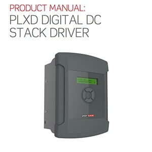
PLXD Manual
